|
“V V” pipe line strainers are designed and built to afford dependable long lasting protection to a wide variety of mechanical equipment like Pumps, Burners, Nozzles, Pressure reducing valves, Traps, Meters & Turbines, etc.
DESING:
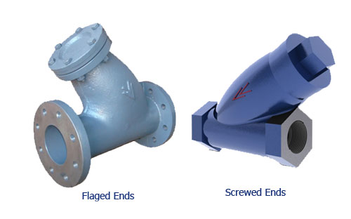
Y type strainers are supplied with:
- Screwed Female Ends.
- Flanged Ends.
SPECIAL FEATURES:
“V V” Strainers are in demand for many applications where straining is required, due to the following special design features:-
- Arc shaped body that is revolved to ensure minimum blockage, less maintenance & less pressure drop with full flow to fluid.
- Fine finish castings to reduce pressure drop.
- Screens are guided in the body.
- Y-type strainers may be installed in downward vertical lines with effectiveness equal to horizontal installation.
- Bodies require long period for cleaning as it has large cross sectional area & more height.
- Large ratio between the clear area thought the strainer and pipe area to limit pressure drop to the minimum.
- A wide variety of corrosion resistant screens, available in a wide range of perforations, provide the answer to straining problems.
MATERIALS:
Strainers body and cover are made in following materials:-
- Cast Iron (IS 210 Gr. FG 200).
- Cast Steel (ASTM A 216 Gr. WCB).
- Stainless Steel (304 & 316).
- Strainer screens: There are two type of screens used in strainers:
Perforated screens
These are formed by punching a large number of holes in a flat sheet of the required material using a multiple punch. The perforated sheet is then rolled into a tube and electric welded together for smooth & permanent joint.
These are relatively coarse screens and hole sizes typically range from 0.8 mm to 3.2 mm. Consequently, perforated screens are only suitable for removing general pipe debris.
Mesh screens
Fine wire is formed into a grid or mesh arrangement. This is then commonly layered over a perforated screen, which acts as a support cage for the mesh.
Screen can either be perforated sheet or wire woven mesh depending on working conditions.
DIMENSIONS:
The main dimensions of these strainers have been tabulated in Table 1. Intel and outlet flange of the flanged valve shall be as follows:-
C.I _ _ _ _ _ _ _ _ANSI B16.1CL-125.
C.S _ _ _ _ _ _ _ _ANSI B 16.5 CL-150(with raised face).
Flanges conforming to other flange standards can also be supplied against specific requirements. Screwed ends strainers are strainers are supplied with female threaded ends as per IS 554/BS 21/ANSI B 2.1.
PRESSURE/TEMPERATURE RATINGS:
Pressure/temperature ratings of strainer confirm the standards mentioned above in DIMENSIONS. The strainers are tested to maximum cold non shock Hyd. Pressure of 20 Kg/cm2. For C.S.
|
|
|
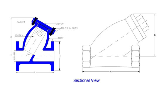
| NAME OF PARTS |
MATERIALS |
| BODY |
CAST IRAN |
| BODY RING |
STAINLESS STEEL/GUN METAL |
| SEAT RING |
STAINLESS STEEL/GUN METAL |
| SEAT |
CAST IRAN |
| GASKET |
COMPRESSED ASBESTOS FIBER |
| TOP COVER |
CAST IRAN |
| BOLTING |
MILD STEEL |
|
| |
| Dimensions |
| Nominal Size |
L |
D (Dia.) |
H (Appx.) |
T (Thickness) |
| mm |
mm |
mm |
mm |
mm |
| 15 |
130 |
95 |
85 |
14 |
| 20 |
150 |
105 |
85 |
16 |
| 25 |
160 |
115 |
90 |
16 |
| 32 |
180 |
140 |
100 |
18 |
| 40 |
200 |
150 |
120 |
18 |
| 50 |
230 |
165 |
130 |
20 |
| 65 |
290 |
185 |
160 |
20 |
| 80 |
310 |
200 |
170 |
22 |
| 100 |
350 |
220 |
190 |
24 |
| 125 |
400 |
250 |
215 |
26 |
| 150 |
480 |
285 |
240 |
26 |
|
| |
|
|